-
-
April 25, 2018 at 6:39 am
-
April 26, 2018 at 1:14 am
peteroznewman
SubscriberHello Fabricio,
ANSYS has mesh controls that can provide a similar mesh. There is a mesh control called inflation that will put a layer of small elements around (or along) a boundary.
If you create the geometry and attach it to your reply, I can show you these mesh controls.
Regards
Peter -
April 26, 2018 at 3:34 am
raul.raghav
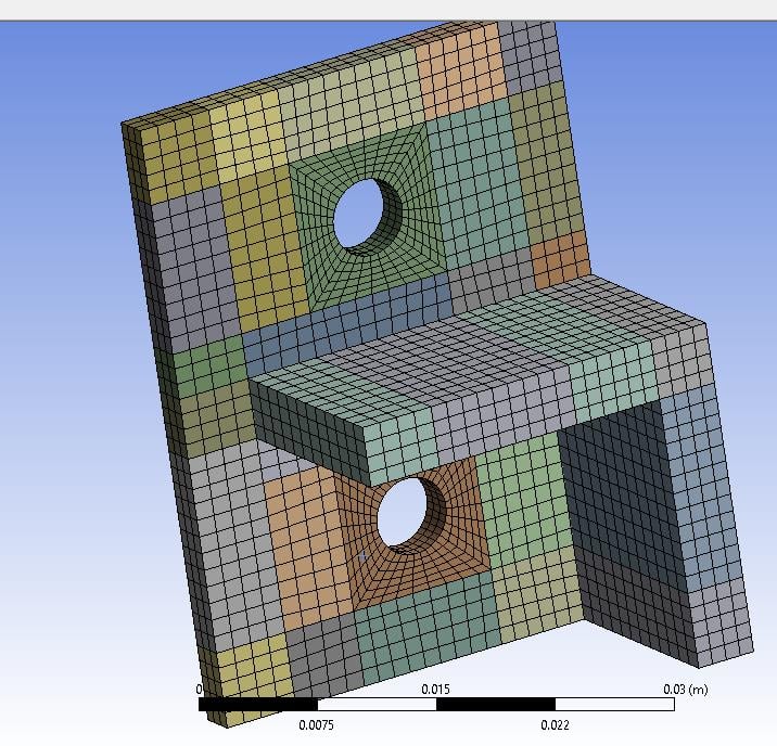
SubscriberPeter is right about the inflation layer. Attached is a workbench archive file which shows two different ways of meshing the geometry.
Refer to the pictures below. The first one is similar to the one you needed help with and the second one is a very easy way of meshing the geometry without any modification to the geometry but with inflation around the holes.
-
May 6, 2018 at 10:55 am
Raef.Kobeissi
SubscriberYou can also use the Cut Cell method to apply a hexahedral mesh. I think ANSYS meshing tool would usually impose a hexa-dominant mesh for simple geometries like this one.
-
May 29, 2018 at 6:24 pm
Fabricio.Urquhart
Subscriber@raul.raghav
Can you attach a Ansys 18.2 file?The beam and the end-plate have different materials (A572 and A36). So I do not know how I match the node between different bodies with bonded contact.
Thank you.
-
May 29, 2018 at 6:25 pm
Fabricio.Urquhart
SubscriberRaef, the Cut Cell method is only to CFD analyse, isn't it?
-
May 30, 2018 at 5:32 pm
raul.raghav
Subscriber -
June 5, 2018 at 10:50 pm
Fabricio.Urquhart
SubscriberRaul, I reached a good mesh dividing the edges and some faces. So the geometry is simpler. And I think that it is not necessary to use "node merge" between the contact, I asked it for Peter, He said it. And results are becoming better. See what happen if I use the node merge.
What do you think about the mesh, In this exactly moment I am doing the convergence test, saving four or five model, increasing the number of nodes and mesh quality.
Thank you very much!!!!
-
June 6, 2018 at 1:20 am
peteroznewman
SubscriberFabricio,
I would divide the face on the base plate along the three planes of the beam that you want to represent as welded to the base plate, then use Node Merge. On other models, I have even created triangular solids to represent the weld bead and bonded that extra material to the model.
Regards,
Peter -
June 6, 2018 at 3:03 pm
raul.raghav
SubscriberFabricio, node merge is important if you want a conformal mesh between the bodies. Without node merge the nodes of the bodies are free to move. Although they might appear conformal with uniform setting of "Multizone", they won't have conformity unless you use node merge. Again the requirement depends on what you're trying to model.
-
June 10, 2018 at 3:41 pm
Fabricio.Urquhart
SubscriberThank you!
I will try it, divide the base plate along the three planes. Yes, I thought about modelling the weld, but for this master thesis I will not do it yet.
Thank you again!!!
-
- The topic ‘How to achieve this mesh?’ is closed to new replies.


- Element type definition – Ansys Workbench
- CONVERTING STL FILE IN TO SOLID
- Varying ply angle in ACP
- The meshing algorithm cannot find matching topology
- Assiging one parameter as thinkness of few shell objects
- [ANSYS Meshing] how to activate curvature for a sizing in a script?
- Discovery 2024 R2 Crashing
- How to create a mapped mesh in a chain link model with stud.

-
1722
-
624
-
599
-
591
-
366

© 2025 Copyright ANSYS, Inc. All rights reserved.


