-
-
December 14, 2017 at 10:51 pm
bushrar
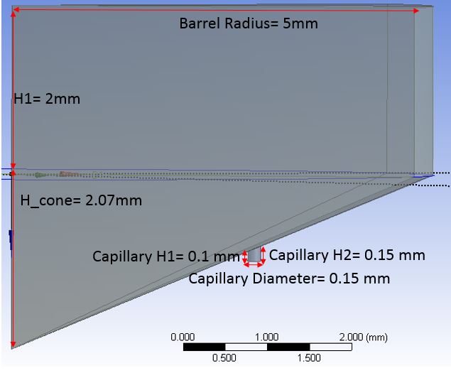
SubscriberThe following geometry consists of a barrel with a conical convergence and a capillary positioned at the middle of the length of the cone, on its surface (Figure 1). The cylindrical capillary has a diagonal entrance. Post processing shows that the center line is 15-20% of the wall shear rate when it should be zero. In addition, the ANSYS calculated wall shear (~30,000 s-1) is 15% lower than the analytically calculated shear rate (shear rate= (4*flow rate)/(Pi*r_capillary^3) =34,500 s-1).
The way I have meshed this geometry was using the adaptive sizing function with the element size 0.023 mm, resulting in about 2.26 million elements. After decreasing the element size to 0.0225 mm, the computational power of my desktop was not enough to run the simulation. I was wondering if anyone has suggestions for improving the meshing of the geometry such the resulting center line shear rate is close to or equal to zero, as well as smoother, even contours on limited computational power.
-
December 16, 2017 at 11:19 pm
Raef.Kobeissi
SubscriberHi.
Have you tried to have 2 zones one for the cylindrical capillary and one for the domain and then apply a manual body sizing for the capillary with a proper inflation layer (defined first layer thick ess)?
Cheers -
December 20, 2017 at 6:05 pm
bushrar
SubscriberIs this supposed to help with reducing the overall number of elements, while concentrating more elements on the capillary?
-
December 21, 2017 at 4:24 am
peteroznewman
SubscriberIn DM I split the capillary tube off the cone, then I split all the bodies down the center of the capillary.
In Meshing, I sized the bodies with a Sphere of Influence in order to have small elements in the capillary, while leaving large elements in the cone end cylinder. I applied a Sweep method to each half of the capillary tube, and applied inflation there. Then I added inflation to the face of the cone. One other sizing control on the edge and a decent mesh is created.
https://youtu.be/VuShUJKS8dk
-
December 21, 2017 at 10:33 pm
bushrar
SubscriberThank you so much for this! This is extremely useful in finding out which local sizing function to use in conjunction with each other in order to get a more refined mesh. I was wondering what dimensions you used on the barrel (including the conical part) and the capillary? This might help me get a better idea how to size the local meshing parameters on the geometry I created. Mine are as follows:

-
December 22, 2017 at 1:15 am
peteroznewman
SubscriberMy Capillary Diameter was 5 mm, so you will want to scale the element size down by a factor of 5/0.15 = 33. So my 0.35 mm element size would need to be 0.011 mm on your geometry. My Barrel Radius was nearly 50 mm.
Check my other video on your other discussion about how to draw an angle between two cones.
You can show your appreciation by clicking "Like" on the posts that are helpful.
-
- The topic ‘Meshing Suggestions needed for Geometry’ is closed to new replies.


-
3155
-
1013
-
956
-
858
-
797

© 2025 Copyright ANSYS, Inc. All rights reserved.


